Multidisciplinary design of a grid fin for a generic high speed missile
MEng Final Project
Context:
In recent times, the use of grid fins is most popularly known to be on SpaceX rockets such as the Falcon 9. The grid fins are used for stability and control on the boosters as they re-enter the atmosphere and land precisely on the SpaceX drone ship. There has been a recent resurgence in interest for the use of grid fins on missile systems due to the benefits they bring. Most notably, grid fins over planar fins offer near zero hinge moments (allowing actuator component downsizing), higher stall angle of attack and smaller centre of pressure variation with Mach number.
Problem:
The design of a grid fins is highly multi-disciplinary. The ideal grid fin with lowest drag has infinitely sharp leading and trailing edges of each of the lattice framework elements. This is impossible to achieve in reality (due to producibility constraints) so a trade-off is required. How do we decide where the compromise should be made?
Project outline:
This project explored the trade-offs between aerodynamic performance, mechanical design, producibility and feasibility that must inevitably be made for use of grid fins on a (generic) high speed missile platform. By using CFD as a tool to analyse performance, the project offered a ‘design 101’ to enable a future designer to navigate this trade-off and be able to balance the disciplines suitably. Through understanding the interactions between these disciplines, various geometrical modifications were explored and investigated and the source of drag (a major drawback of grid fins) was identified. A future designer can now choose the best compromise of design features to best suit the available producibility capabilities. Lastly, heating estimates were calculated and various methods compared to eventually allow preliminary material selection for such a grid fin design.
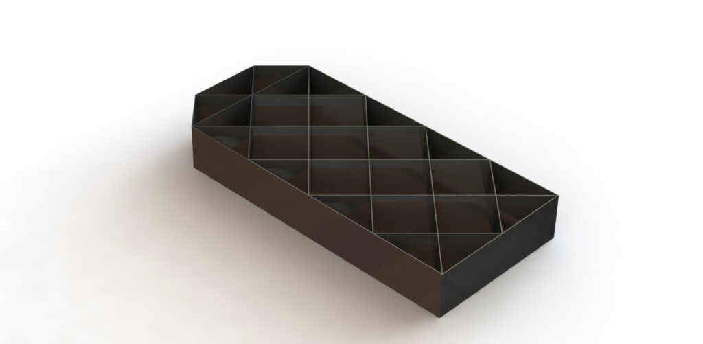
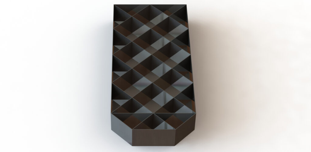
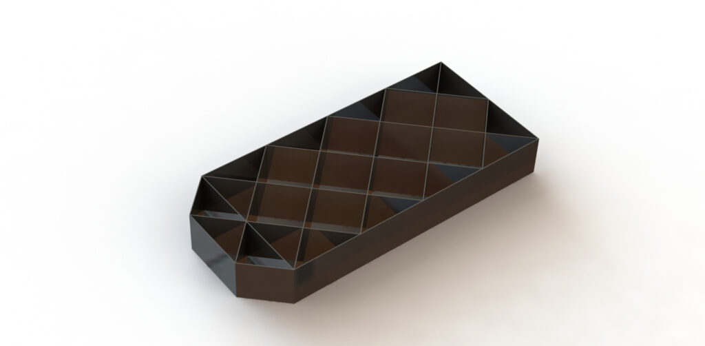
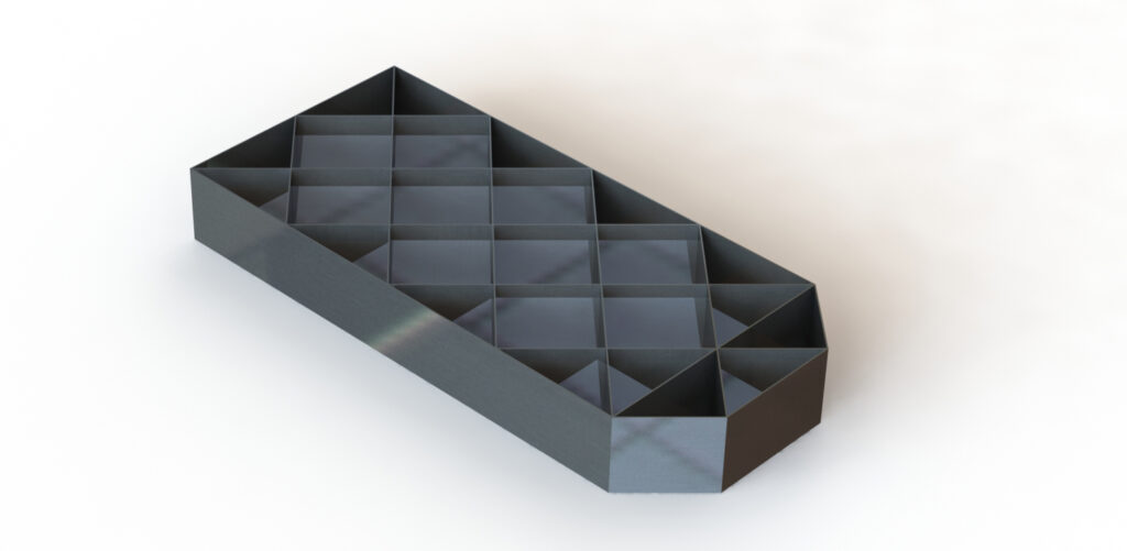
CAD model of the grid fin used for the CFD studies and design analysis.
After identifying the problem and design motivation, existing applications of grid fins were considered. A complete literature review was also conducted to deduce the strengths and weaknesses of previous work in the field. Grid fin use was particularly prominent on the Russian R-77 Vympel missile and so this was used as a baseline for the initial CAD model. For this project, a unique 3 stage approach was adopted to be able to simplify the CFD simulations and be able to clearly distinguish between the effects of various design decisions.

The 3 stage approach involved breaking the design problem down into 3 steps; two 2D simulations and one 3D simulation. The 2D simulations allowed me to understand the 2D aerodynamic and design effects such as the effect of varying taper (at leading and trailing edges), varying thickness to chord ratios, varying chord to spacing ratio and any off-design 2D flow features. Stage 3 then gave me an understanding of the 3D flow features and how geometrical modifications may ease producibility concerns while also providing a performance benefit.

The above animation demonstrates how the two sections interact as chord to spacing ratio (c/s) is increased. This involves a shockwave boundary layer interaction and is a source of drag. This helped inform the physical spacing required for a grid fin web at a particular Mach number (M=3 shown above).
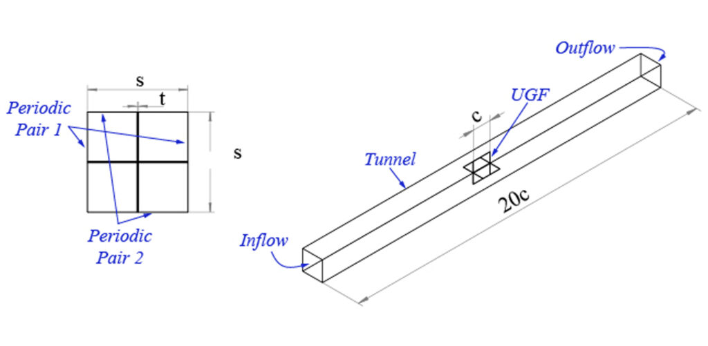
To avoid a full 3D CFD simulation of the grid fin which would be very computationally expensive, the setup was simplified to a unit grid fin (UGF) approach where a small section was taken and periodic conditions were applied to replicate the full fin. This reduced the computational cost of the simulation whilst still being equally powerful for obtaining the intended results.
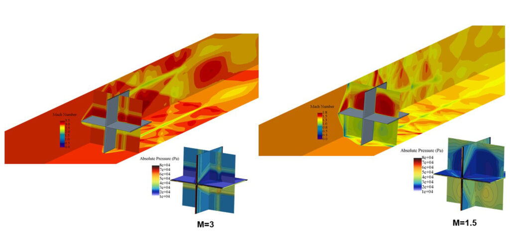
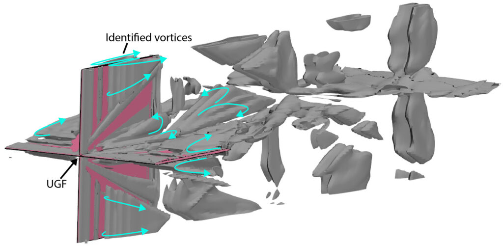
At a Mach number of 3, for the chosen grid fin geometry, little interaction is observed between the plates of the UGF element. As expected and is typical with grid fins, their performance suffers at slower speeds; at M=1.5, strong interactions within the pressure regions is seen and this corresponds to a drag increase which the designer must aim to avoid. The source of vortices and their peeling characteristic was also identified through the CFD simulations, allowing compromises with geometry to be made accordingly.
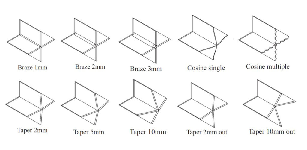
Lastly, several variations of geometrical features were explored to identify any possible sources of performance benefit which may also correlate with a design that is easier to produce. Unfortunately, all of the configurations resulted in a net increase in drag as compared with the stock configuration and this was highlighted within the design guide.
As a result of the studies performed in this project, I was able to produce a design guide to inform the decisions of a future grid fin design engineer. The recommendations made were:
1) Aim to produce a 2/3 taper on the edge as a best compromise between producibility and drag performance.
2) To prioritise the surface finish and accuracy of the leading edge rather than trailing edge of the elements.
3) Aim for minimum thickness to chord ratio.
4) The R-77 geometry poses no risk of choking the flow.
5) Aim to avoid brazing of the plates as it carries a large drag penalty.
6) Avoid any geometrical modifications to the trailing edge.
7) To prioritise the material choice of the leading edge for heating and low drag requirements.
Additionally, I was able to recommend that future grid fin designs would best benefit from additive layer manufacture (ALM) techniques such as metal 3D printing. These would allow a superior surface finish and avoid the need for brazing, which carries a significant drag increase. Also, ALM would unlock the possibility of intricate geometries, such as varying lattice cell sizes or an unframed grid fin.
Like many complex engineering problems, the multi-disciplinary nature of this project was apparent. Through the studies performed, I was able to guide an engineer on how to navigate these disciplines and ultimately achieve the most impactful and highest performing solution. This project was supported by industry and the outputs were directly used for development activities within the company.
Skills developed:
Research, computational fluid dynamics (STAR-CCM+), engineering analysis, aerodynamic design, CAD modelling (Creo and Solidworks), MATLAB, design methodologies, hypothesis forming and testing, presentation.