Drone Flight Case and Launch Station
A bespoke solution for drone storage, transportation and flying.
Problem:
Off the shelf solutions for drone storage have a single purpose and are useless once the equipment is taken out of it in the field. They are one-size-fits-all and lack any customised features or implementations.
Objective:
Brainstorm, design and build a tailored solution that would enable:
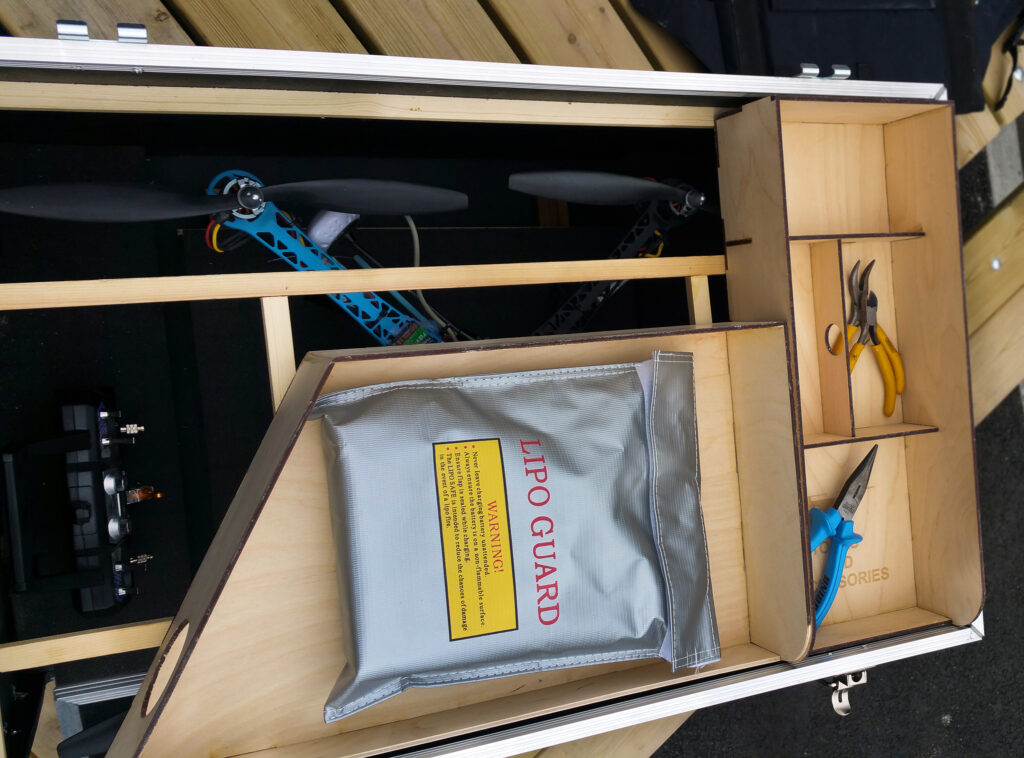
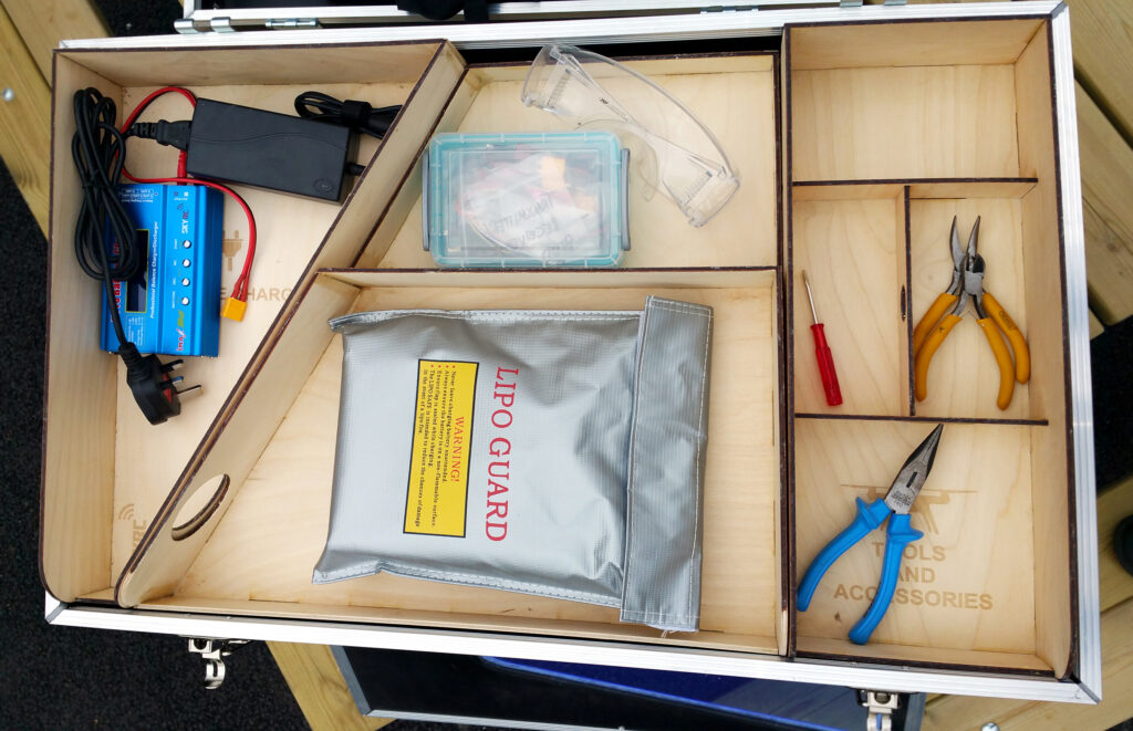
– Adequate drone, equipment and tool storage.
– Effortless mobility (equipment > 5kg).
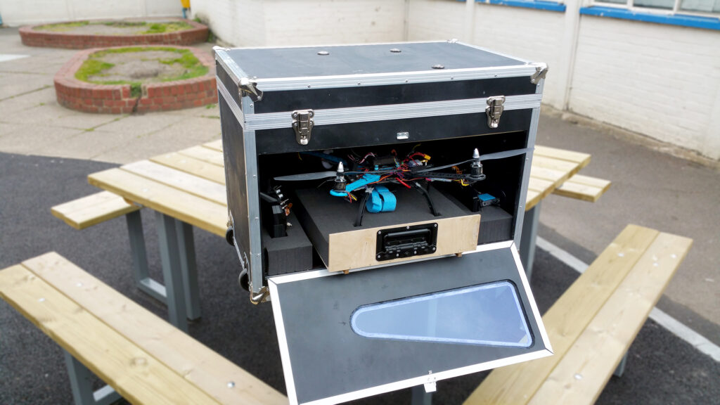
– A launch platform to enable flight from uneven terrain.
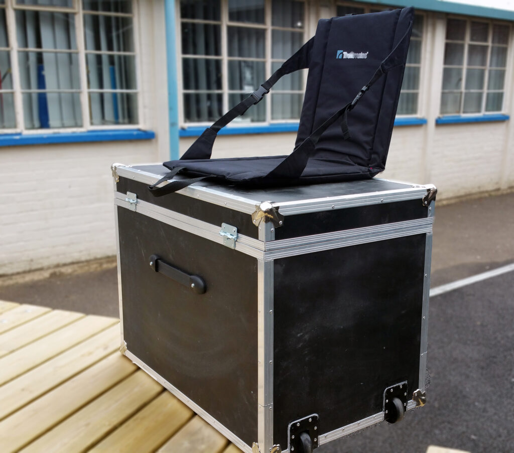
– A seat for flying long duration missions.
– Durability for long distance transportation and/or shipping.
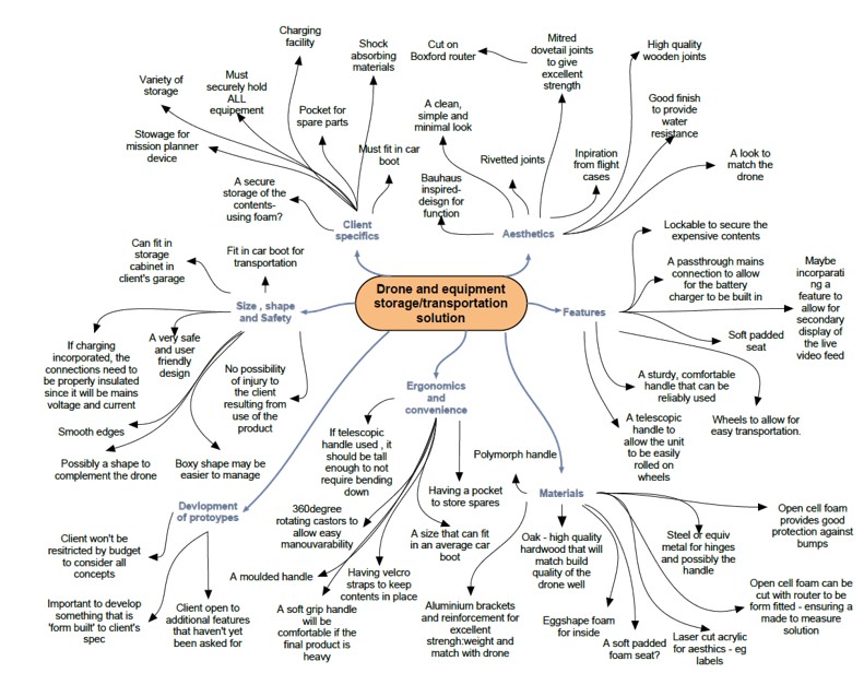
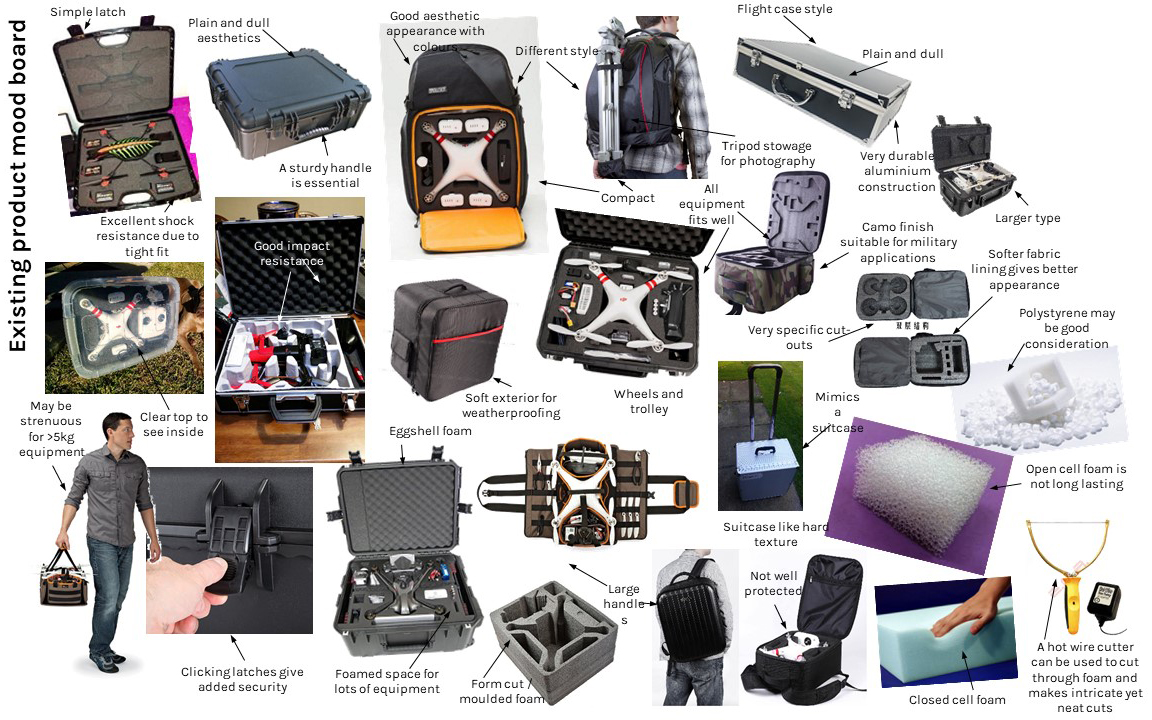
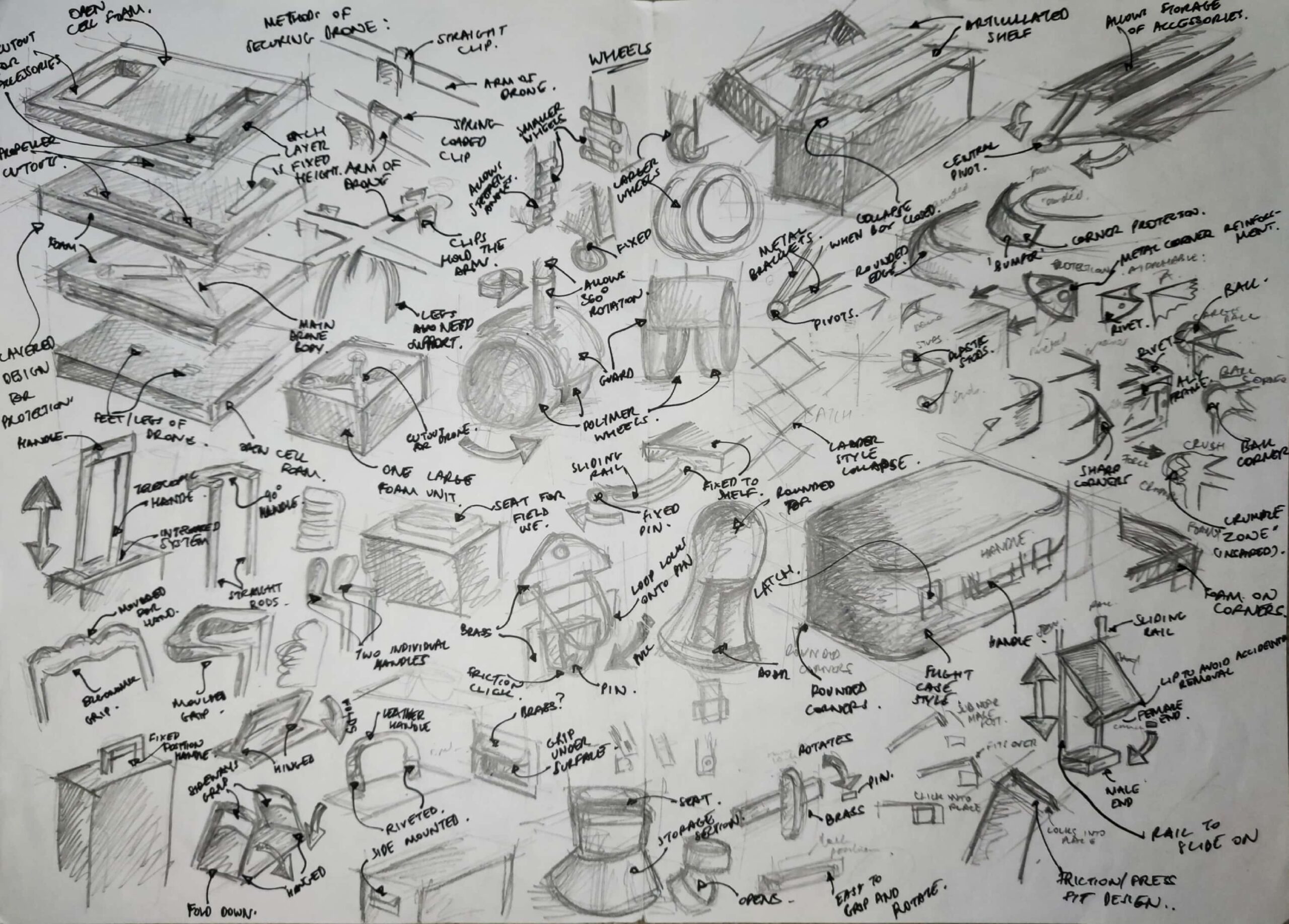
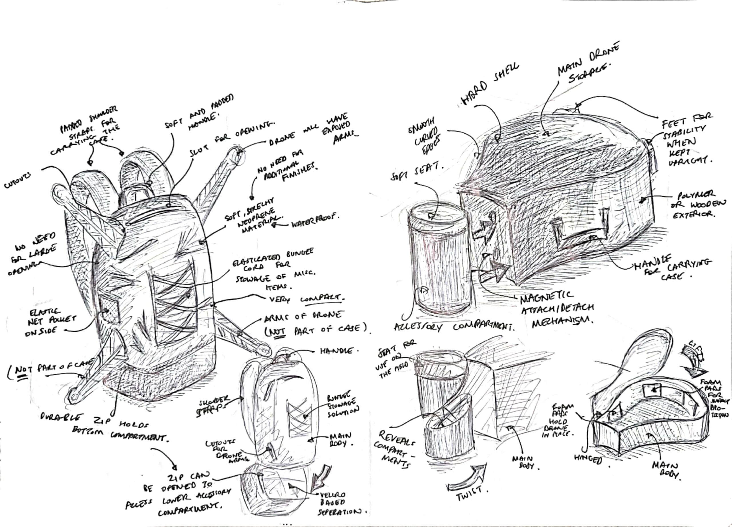
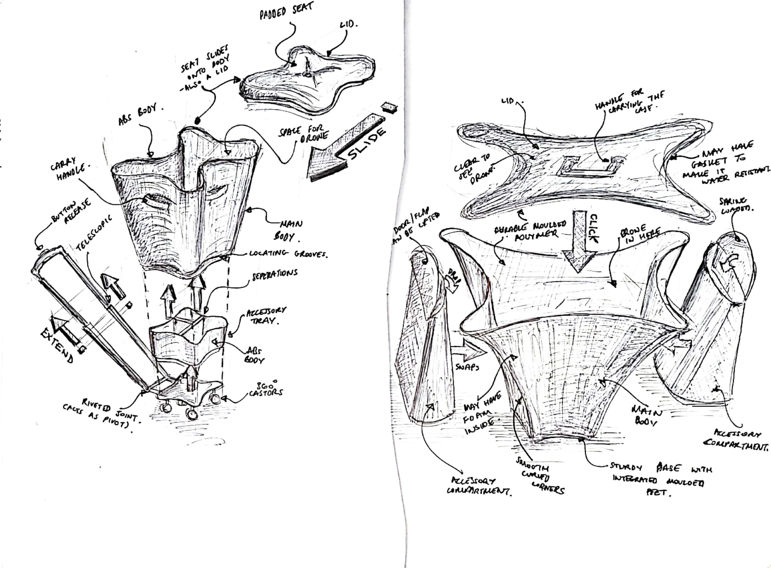
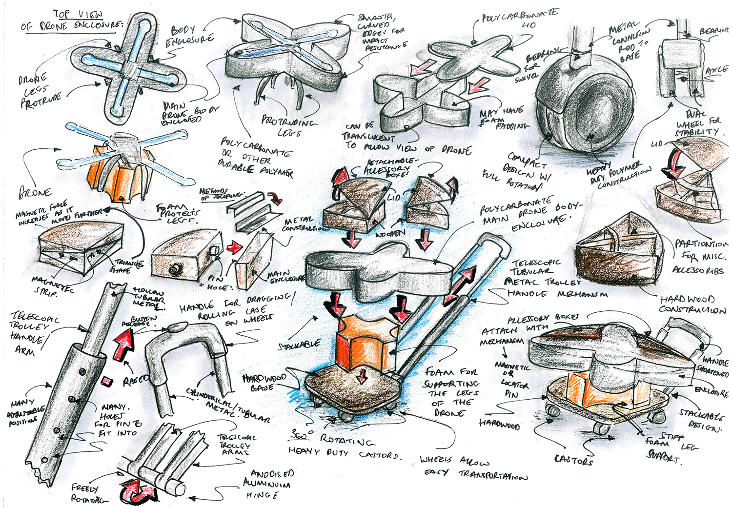
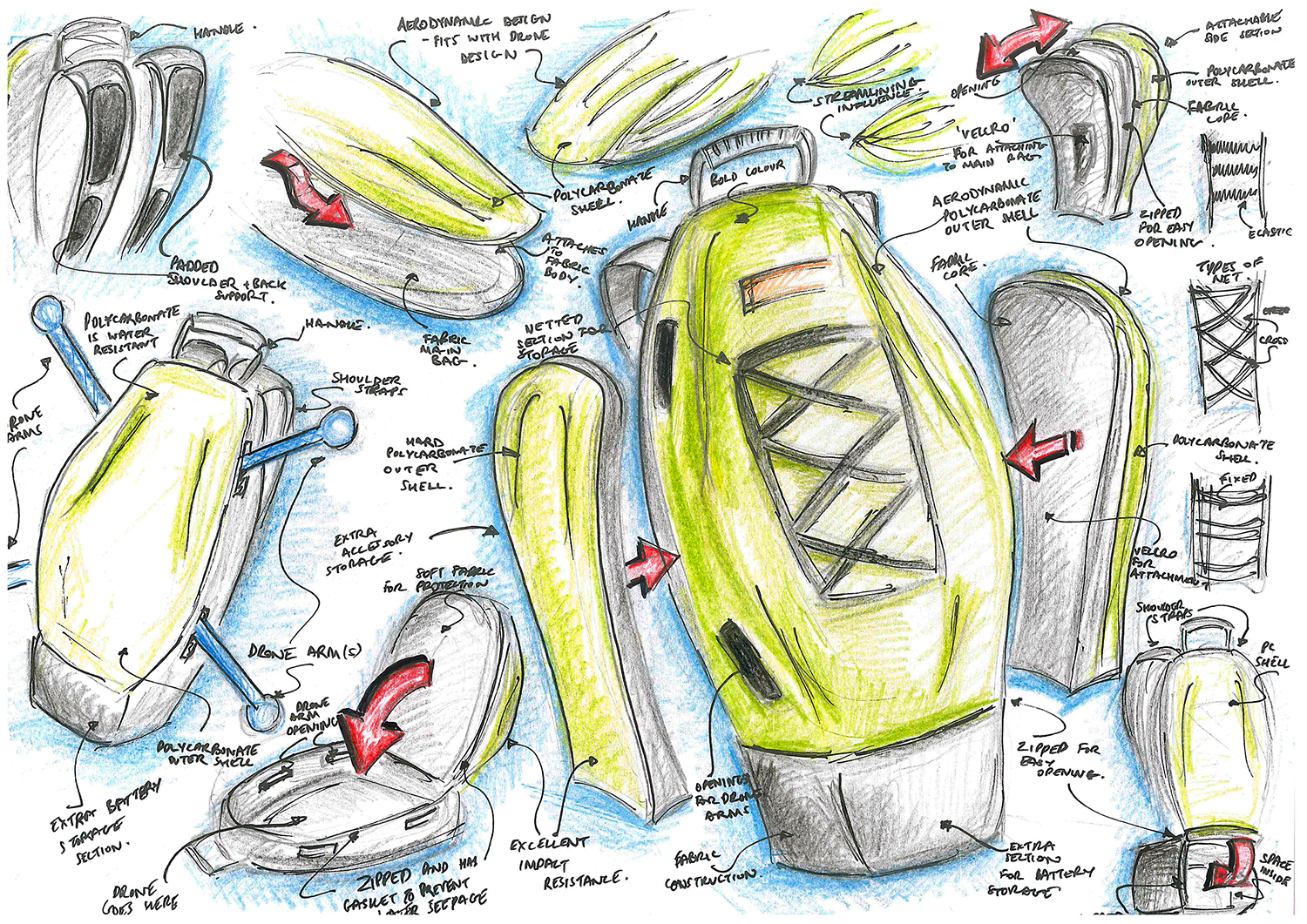
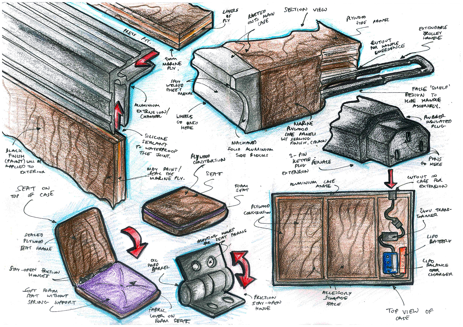
By first identifying the problem, a design brief was put together keeping the user at the centre of the design process. The typical storage location, its dimensions and flying locations were photographed to gauge suitability of mobility solutions. Finally the profiling process ended with looking at existing products, a mood board and anthropometrics to determine suitable dimensions for the product. Below are some rough sketches of me ‘thinking on paper’ at this initial stage of the process.
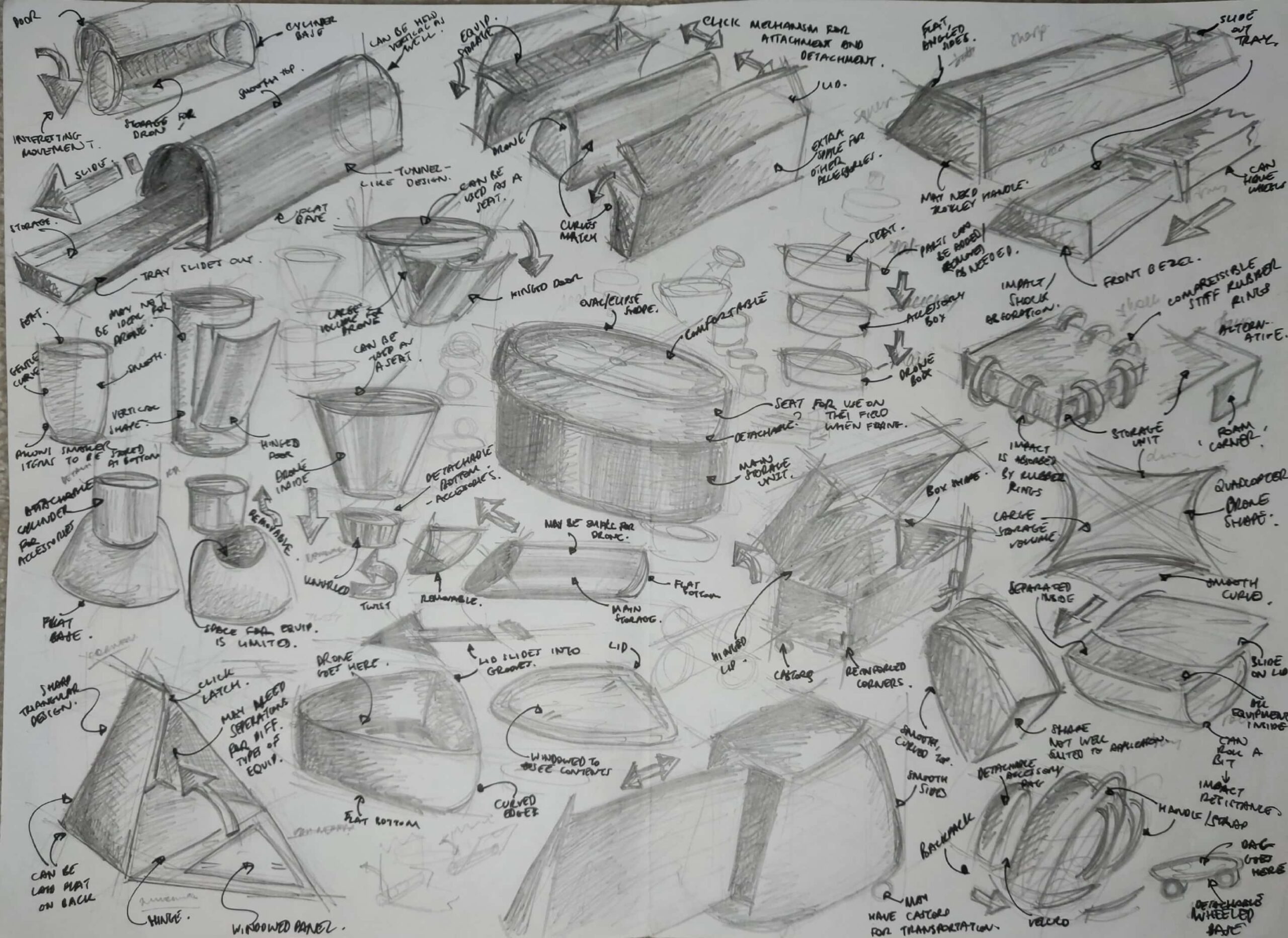
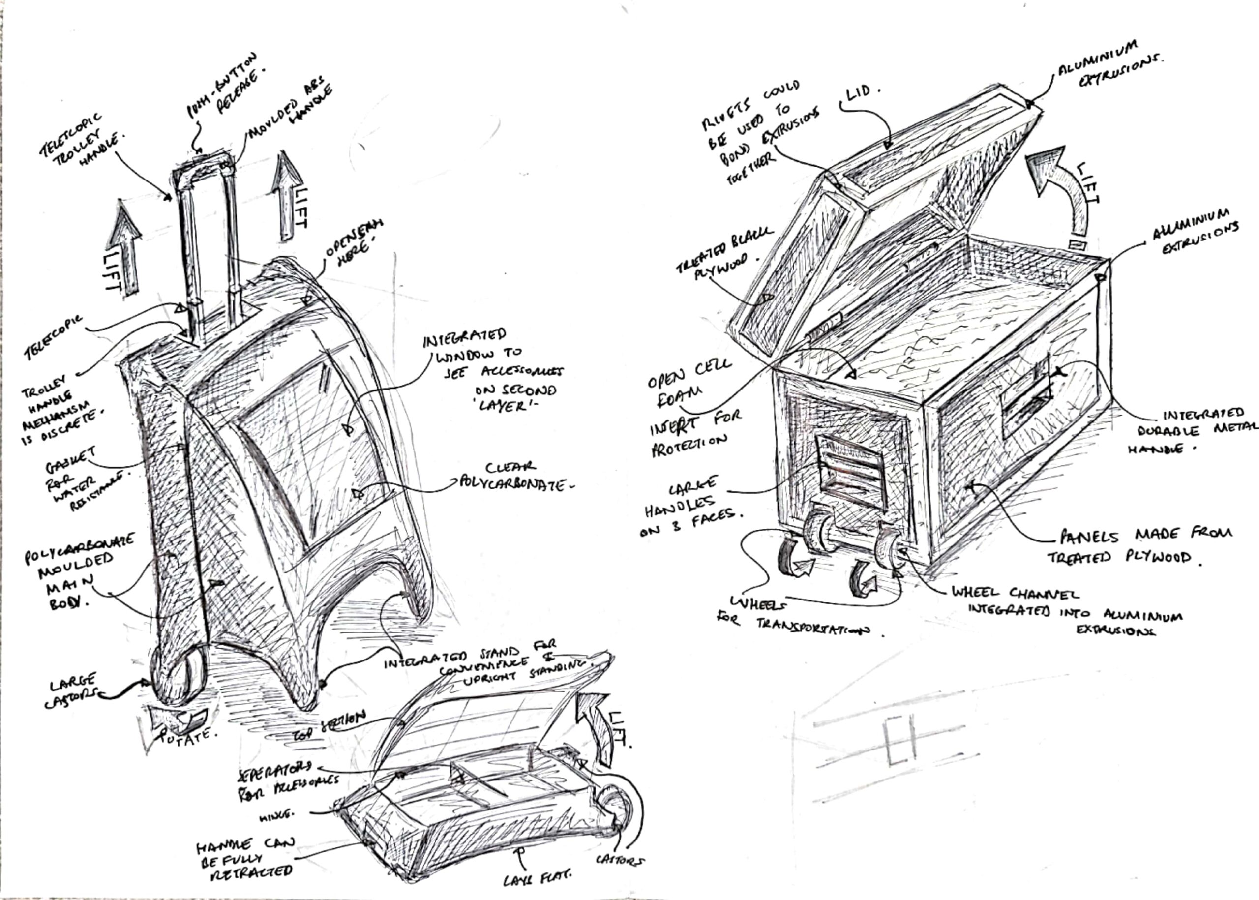
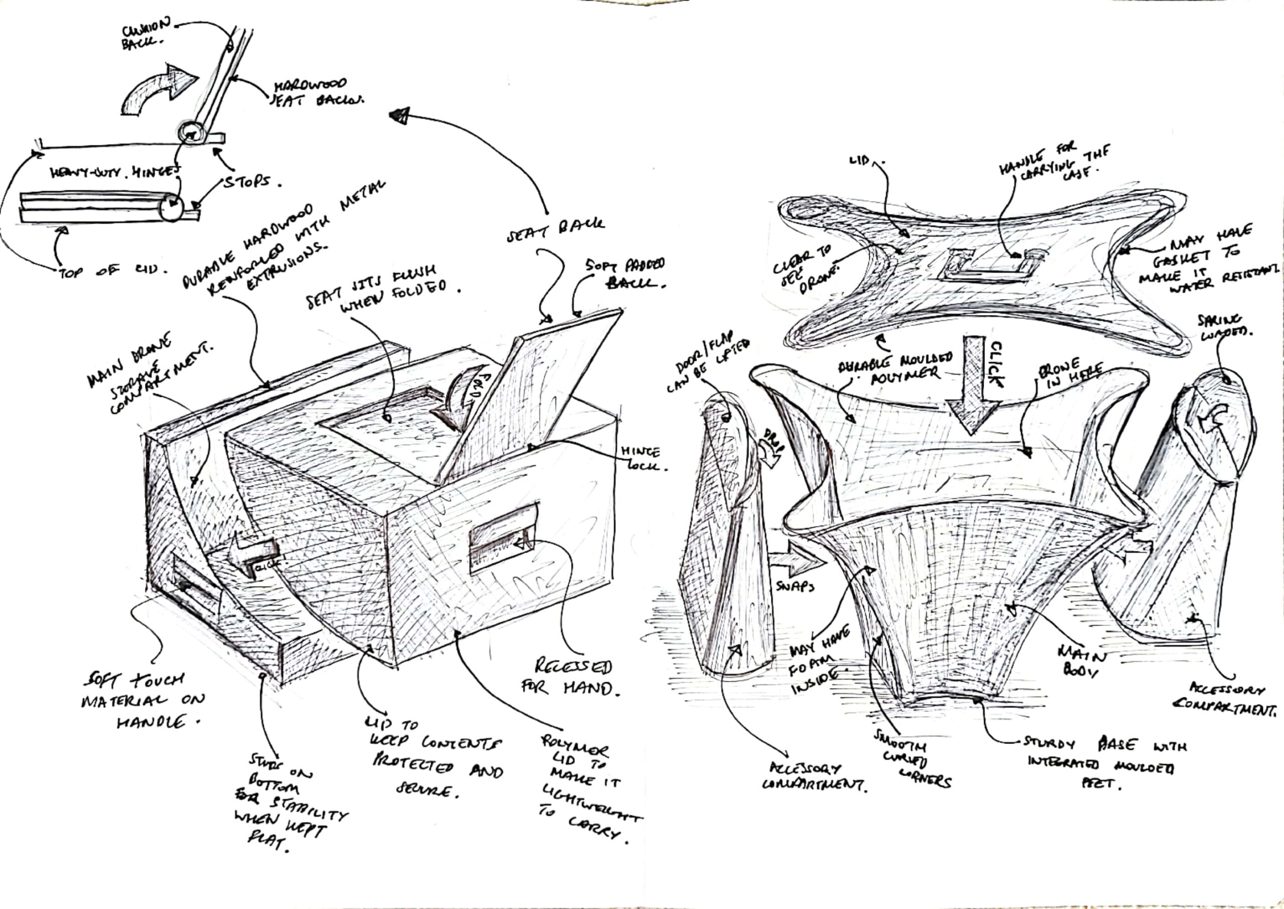
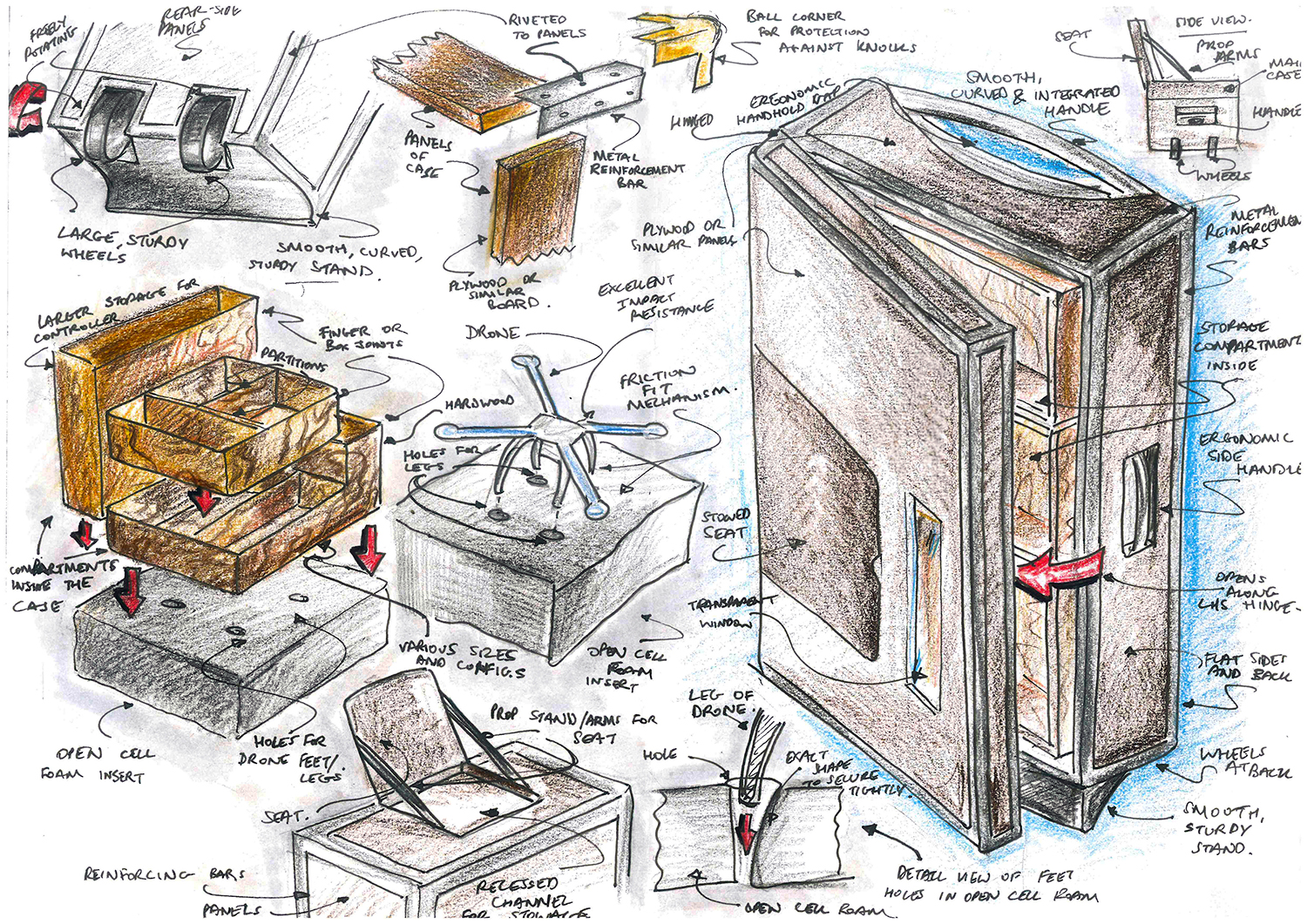
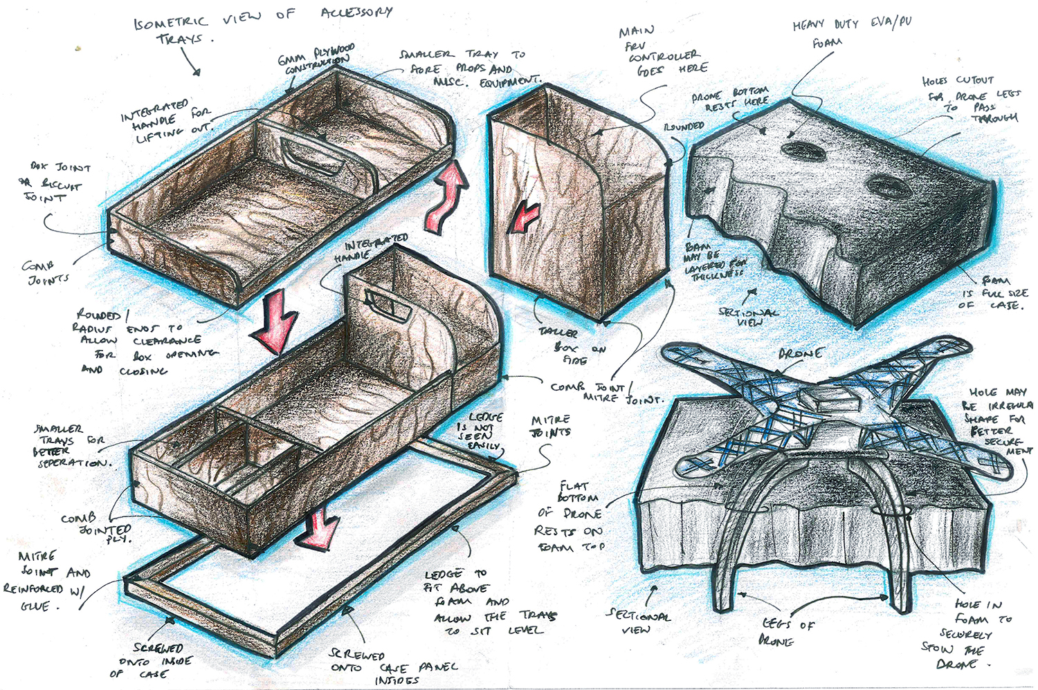
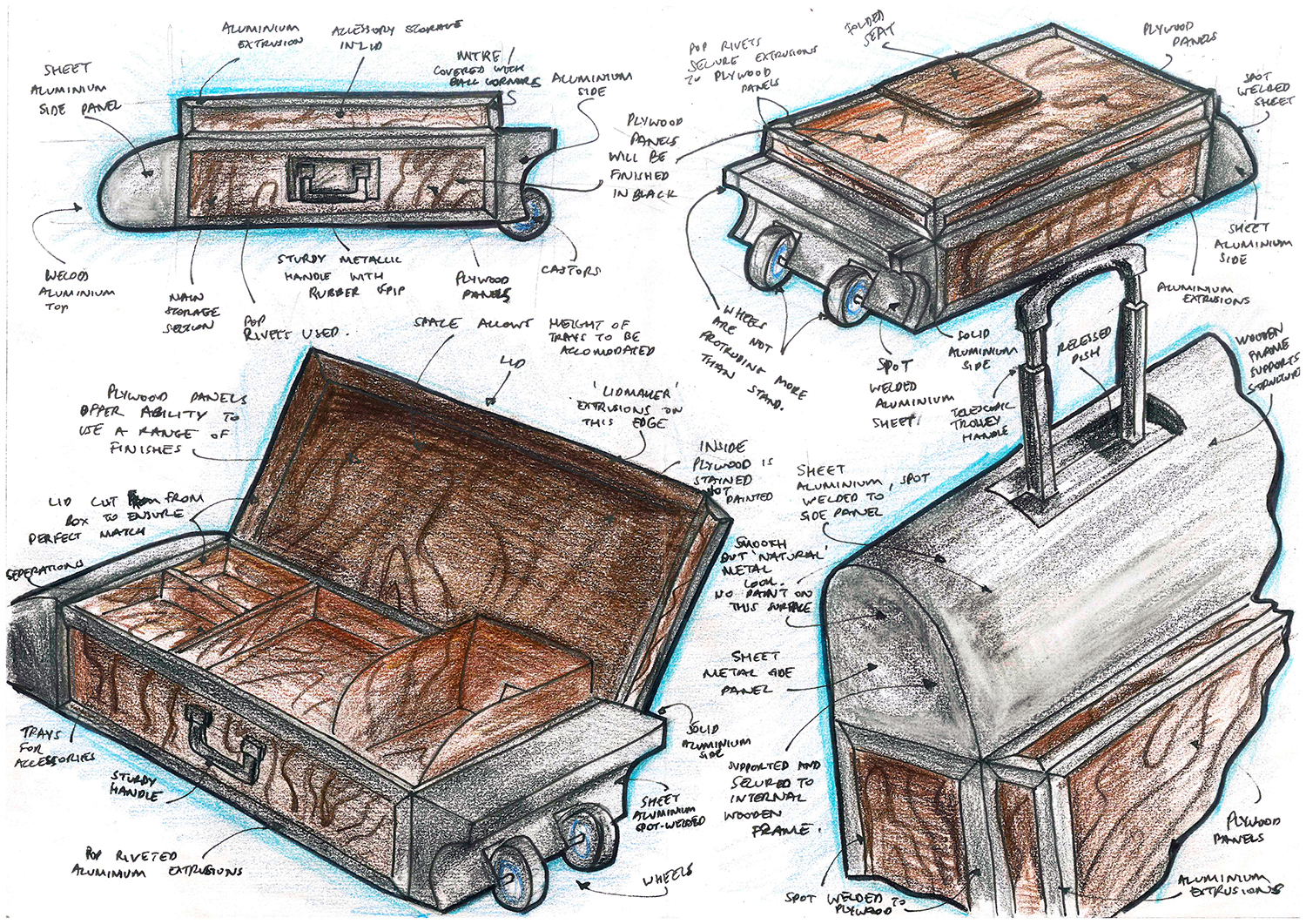
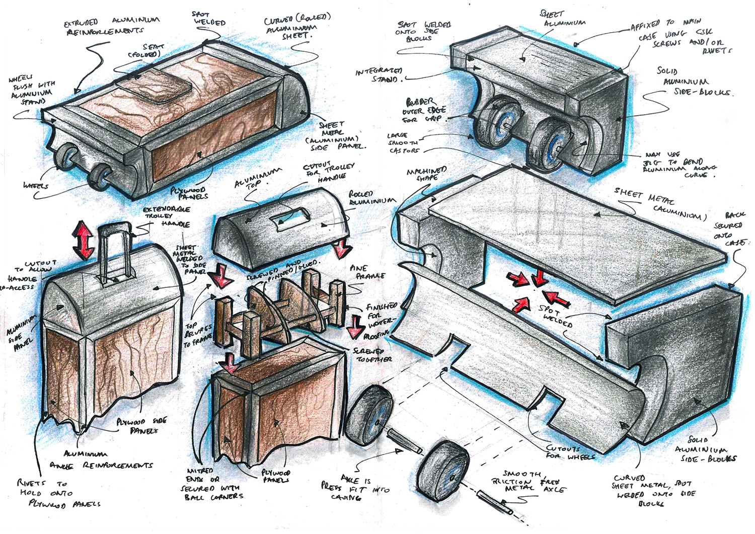
After developing some initial concepts, the design brief and specification was reviewed to then produce quick sketches of more developed ideas.
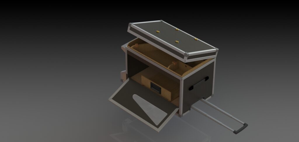
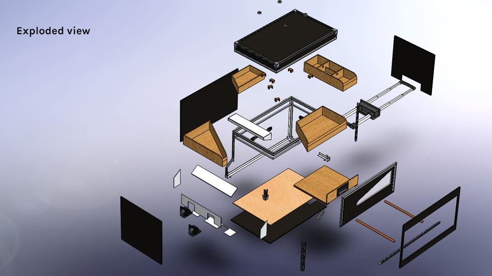
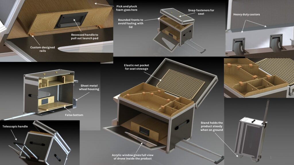
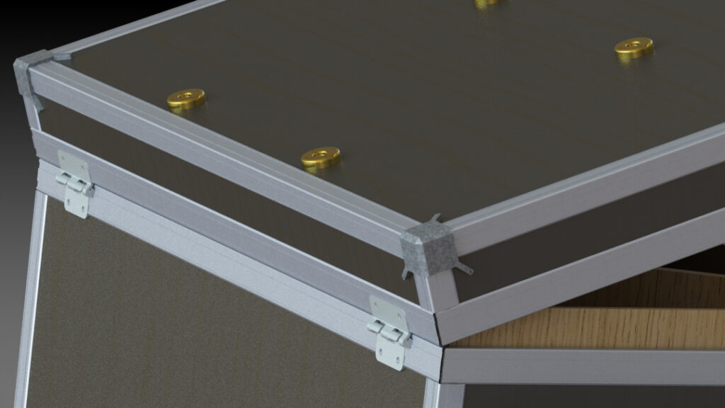
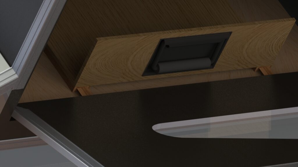
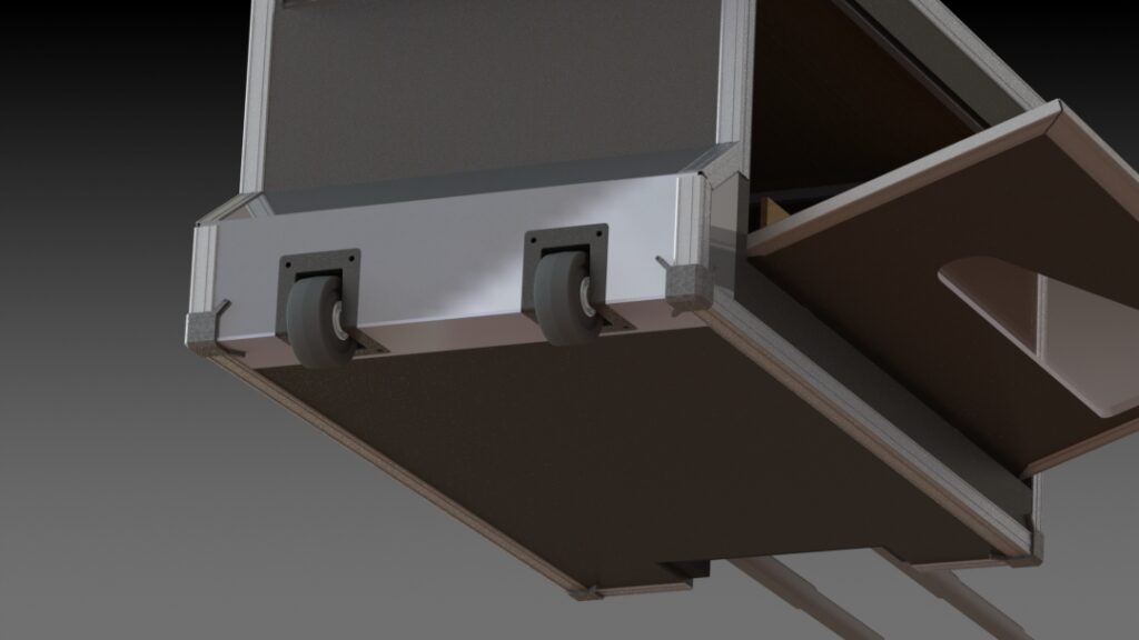
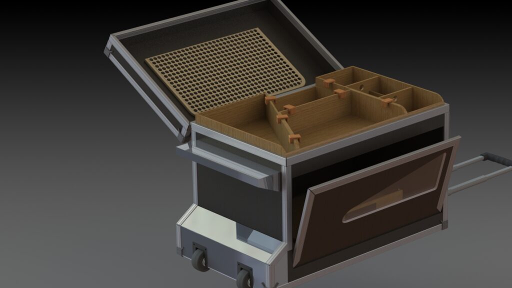
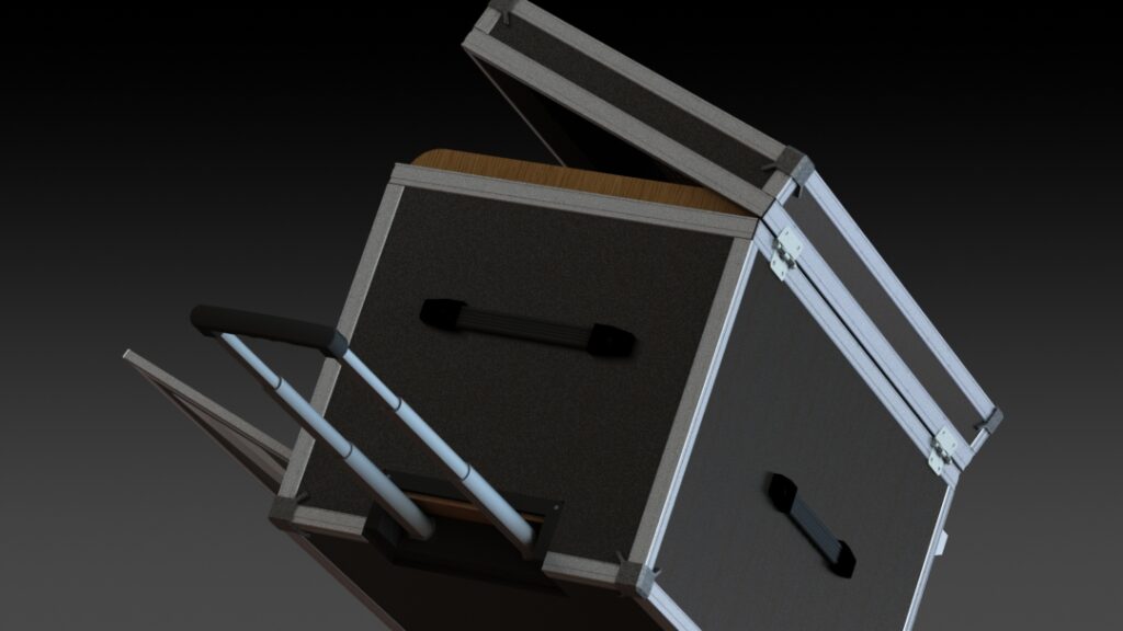
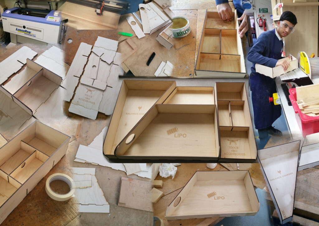
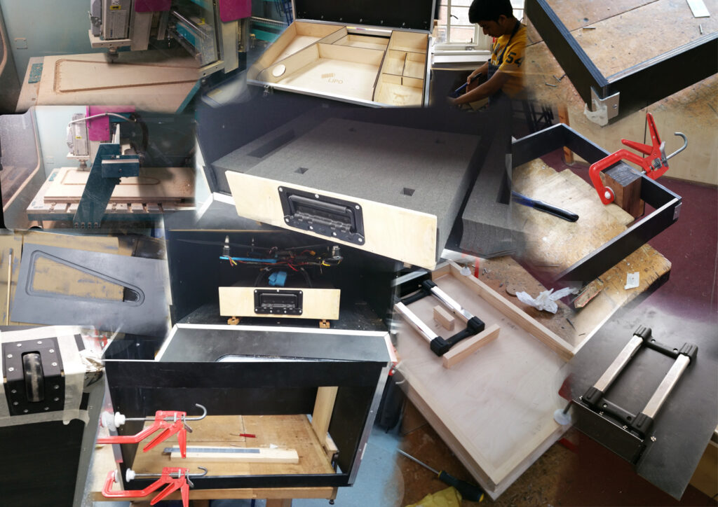
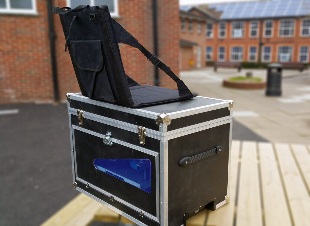
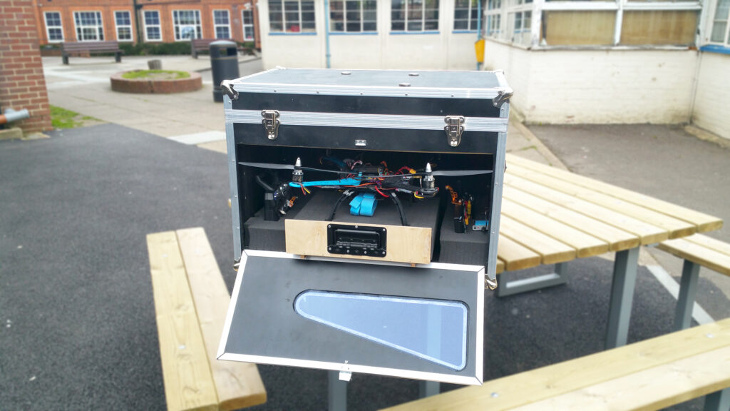
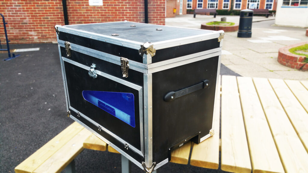
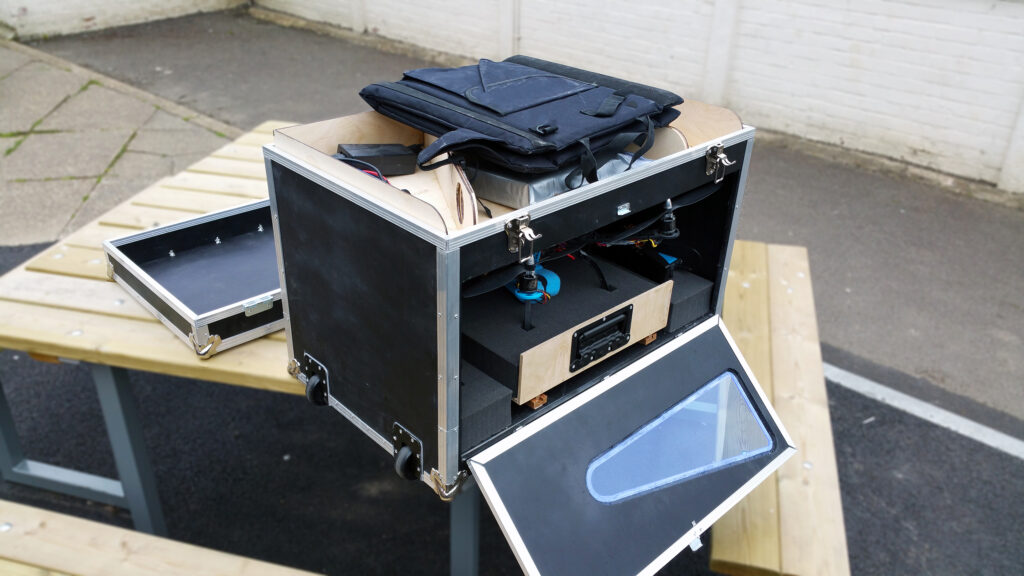
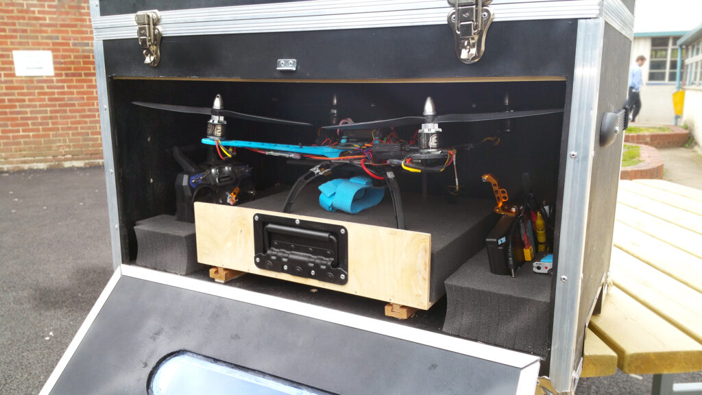
I had set a budget of £100 for the whole project, including materials and the cost of using equipment such as the laser cutter or CNC router. Working from this, as well as the requirements set out initially, flight cases were an ideal starting point given their durability and ruggedness from a combination of metal and wood. I proceeded to down-select from my concept designs to finalise a design inspired by this but heavily customised it to suit the design brief set out. The design had to also double as a launch platform, so a slide out tray was incorporated to act as both a storage location and landing pad for the drone. A bespoke rail system and pick-and-pluck foam was used to enable protection for the equipment. The side panel was hinged and recessed to allow an acrylic window, with a drawbridge style opening for easy access of the landing pad. Furthermore, a unique tray system was designed for the upper section to be able to house all of the additional tools, allow battery charging and stow the seat when not clipped to the top. Simple button fasteners worked great for as a securing mechanism for the seat. Heavy duty castors and an extending trolley system was added for ease of moving the case.
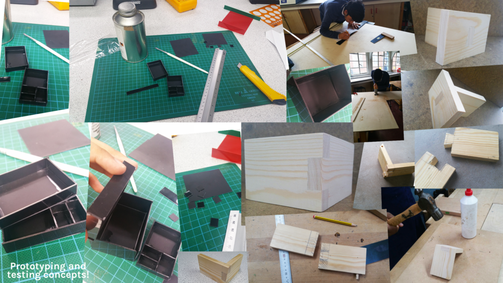
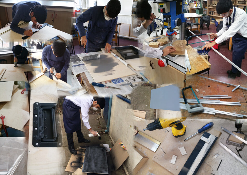
After several iterations of CAD designs (using Solidworks) and prototypes to finalise features of the product, I began the most enjoyable part of it; making! Using a variety of hand tools and workshop tools such as laser cutting the trays from a flat sheet, riveting the panels to aluminium extrusions, building jigs to ensure assembly accuracy and a CNC router to cut oddly shaped panel recesses, the whole manufacturing process took around 30 hours.
The drone, batteries and equipment could then be tested to fit in the product!
Thinking back to where the idea for this began, and the problem itself, it was important for me to conduct a self evaluation of the final result. Like any engineering problem, the best solutions are always iterative, and this was only the first iteration!
Reflection:
Overall, I was proud of the final outcome especially given it was my first time using much of the specialised workshop equipment. A problem had been identified and the final result of the process produced a tangible product to solve this problem. The product allowed ample storage for all drone related equipment, easy transportation to the site using the wheels and trolley handle, a convenient slide out tray from which the drone could be launched directly, a seat for comfort during long flights and finally a high level of protection against impact during shipping.
Nevertheless, several areas of improvement had been identified and I would love to have a chance to work on these if starting over! Namely, some of these were:
– It looks boxy! Aesthetic improvements to differentiate it from a traditional flight case. Access to steam bending moulds / equipment for use on the wooden panels would enable more attractive shapes to be manufactured. Currently, the access to workshop tools was fairly limited in this sense.
– An integrated battery powered LED strip on the slide out tray to provide easy recognition of the ‘landing pad’ using the onboard camera in flight. The current solution is difficult to spot when flying ~100m high and using a low resolution flight camera.
– A more elegant solution for the side panel hinge and stop assembly. The current solution has an arguably crude solution to stow the side panel closed. In future, a magnetic frame could be incorporated, eliminating the need for a latch and reducing the weight of the assembly.
– Building in the seat into the product rather than using a COTS product. Although currently limited by the available workshop equipment, a future solution could look at a folding plywood seat integrated into the lid of the case. The concept of kirigami seems like an interesting avenue to explore to help with this!
Skills developed:
Idea sketching, concepting, physical prototyping, CAD modelling (Solidworks), CAM techniques (laser cutting and CNC routing) and manufacture using various hand tools.
